

To most individuals antenna design and principle is way of a black artwork. Nevertheless, with a bit of little bit of eagerness and keen to be taught anybody can construct their very own antenna design with good outcomes. That is finest demonstrated by Pepijn de Vos’ journey on designing and prototyping a printed PCB antenna for GPS frequencies.
The motivation for the challenge got here after talking with just a few colleagues at an MCH meetup whom labored with maps functions. MCH (Might Include Hackers) is a gathering that takes place in Amsterdam and is organized by volunteers. Its sole goal is to convey like minded people collectively to share information, technical developments, experiments, hacks, and most significantly join with different people with comparable pursuits. Like many different technical meetups, badges had been distributed to encourage studying and hacking.
MCH meetup badge (📷 :MCH2022)
The purpose of this challenge was so as to add GPS capabilities to the badge. Moreover, the true problem and take a look at was designing and prototyping a customized antenna for GPS frequencies. To start, some background analysis was completed which included reviewing patch antenna design and principle info from the next textbooks: Antenna Principle: Evaluation and Design, Microstrip Antenna Design Handbook, and Circularly Polarized Antennas. Utilizing info discovered from these texts, the size for an oblong path antenna had been calculated for the L1 GPS frequency of 1574MHz. A brief Python script was put collectively for the computations, which is proven beneath.
As soon as dimensions had been decided, the subsequent steps entailed calculating the 50 Ohm hint width wanted for the precise PCB dielectric and figuring out find out how to make the antenna circularly polarized. It seems designing a circularly polarized patch antenna just isn’t precisely straight ahead. Nevertheless, it may be achieved by truncating the corners of the oblong patch. With place to begin decided for the antenna, the subsequent steps concerned numerous simulation. At first OpenEMS was used since it’s open supply and free. However after yielding odd outcomes that didn’t make a lot sense, it was decided a special route would should be taken. Having seen a whole lot of simulation work accomplished utilizing Sonnet software program elsewhere and figuring out free trial licenses can be found, the remainder of the simulation and design work was accomplished utilizing Sonnet.
Simulated outcomes of truncated patch antenna (📷: Pepijn de Vos)
Working with Sonnet for the primary time got here with its personal studying curve, although with the assistance of their assist employees an optimum antenna design was converged upon in a short while. This was primarily completed by operating parametric sweeps on totally different geometries of the patch antenna. Naturally, the subsequent step is to start to convey the antenna to life. Utilizing KiCAD a structure was created with the specified dimensions. The truncated patch antenna, an oblong patch antenna, and a microstrip for calibration had been all exported into Gerber recordsdata. These had been then delivered to the native hackerspace, Tkkrlab, to mill out a two sided PCB utilizing a CNC machine.
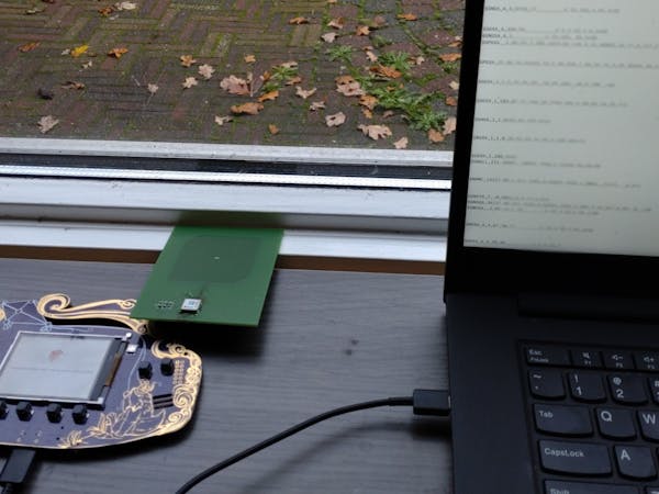
The ultimate steps included the thrilling a part of testing the design. First, the return loss or S11 was measured utilizing a LiteVNA. This confirmed a S11 response that carefully matched the simulated outcomes. Subsequent, the u-blox MAX-M10S GNSS module was acquired. This low energy, asset monitoring machine will finally be what allows GPS on the badge. After tinkering with the I2C interface, the antenna and module mixture had been related to the badge and NMEA messages started showing on the show. The antenna was working, receiving satellite tv for pc communications, and the situation was discovered! Total, the method of antenna design and prototyping yielded a profitable PCB patch antenna for GPS frequencies.